A table saw's fence was adjusted to take 1/4" (7mm) off one end of the polycarbonate sheet. The measurement yesterday indicated that 8mm should be take off but the saw's ability to cleanly cut this plastic and the margin of error suggested that the first cut should leave 1mm extra. The cut was successful and the sharp blade made a clean edge on the plastic sheet. The size did not fit so more plastic was trimmed until it made a sheet with the dimensions of


The first switch mounting was attempted by clamping a piece of wood from the user's side. The wood had to be narrow so it would press the plastic like a user would press it. Using a wide piece of wood might flatten the plastic which would not accurately simulate a person pressing. The first switched was positioned but unable to be mounted. This model of switch lacked a lever arm which was useful in retrospect because it added distance between the contacting surface of the plastic sheet and the position of the mounting holes. Different switches will be purchased.


 Journal Page
The rest of the posts for this project have been arranged by date.
This blog, including pictures and text, is copyright to Brian McEvoy.
2015-01-22 (Th)
14 1/8" x 12 7/8"
359mm x 327mm
In the end 3/8" (9mm) was removed. This resulted in sheets which fit securely but each quadrant seemed capable of being pressed independently of the other quadrants.
Measurement of table saw
First cut made with table saw
Excess material still present
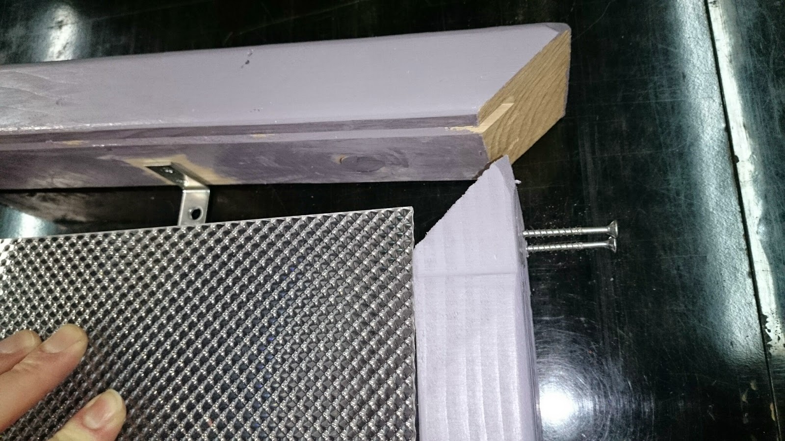
Final length of polycarbonate sheet
The first switch mounting was attempted by clamping a piece of wood from the user's side. The wood had to be narrow so it would press the plastic like a user would press it. Using a wide piece of wood might flatten the plastic which would not accurately simulate a person pressing. The first switched was positioned but unable to be mounted. This model of switch lacked a lever arm which was useful in retrospect because it added distance between the contacting surface of the plastic sheet and the position of the mounting holes. Different switches will be purchased.
Plastic mounted in place and enclosure reassembled
Clamp used to simulate button press
Positioning switch
To do:
Cut 8mm from polycarbonate sheets- Buy Switches with rollers
- Install Switches
- Test ISD1820PY chip
- Test for correct GND/Vcc hookup
- Test with 5VDC
- Create circuit board
- Designate all components
- Design schematic of components
- voltage regulators
- line level converters
- opto-Isolators
- power terminals
- mother-daughter board connectors
- device inter-connection signals
- auxiliary posts for musical devices
- jumper for alt modes
- and supporting components.
- Design layout for single layer board
- Make a parts list
- Order parts list
- Print circuit board
- Install components
- Test + Verify
- Make all documentation public
A list showing of all the final posts of COMPLETED projects.
Disclaimer for http://24hourengineer.blogspot.com/
This disclaimer must be intact and whole. This disclaimer must be included if a project is distributed.
All
information in this blog, or linked by this blog, are not to be taken
as advice or solicitation. Anyone attempting to replicate, in whole or
in part, is responsible for the outcome and procedure. Any loss of
functionality, money, property or similar, is the responsibility of
those involved in the replication.
All digital communication regarding the email address 24hourengineer@gmail.com becomes
the intellectual property of Brian McEvoy. Any information contained
within these messages may be distributed or retained at the discretion
of Brian McEvoy. Any email sent to this address, or any email account
owned by Brian McEvoy, cannot be used to claim property or assets.
Comments
to the blog may be utilized or erased at the discretion of the owner.
No one posting may claim claim property or assets based on their post.
2015-01-22 (Th)
Comments
Post a Comment