Tim and I wanted to do a slow with a more consumer slant. We focused on RFID access because anyone can buy an RFID tag and an RFID lock for their door, bicycle, safe, gun and computer. RFID tags are available in different form-factors like stickers, key fobs, and wearables like rings and bracelets. One person has already told me they were inspired to automate their bedroom after this show.

A wiring diagram was sketched on a sticky note and the potentiometer was wired accordingly. The colors were not significant since once they entered the RJ45 junction box they have another color code and that is the one which will matter when it mates with the control enclosure side.

Storing the gear board was getting cumbersome. It had to be kept flat and that took a lot of space. Or, it could be kept vertical but it was prone to slipping and falling over. Inexpensive shelf brackets were purchased and installed upside-down so they could act as stands.

The first handy box was mutilated while modifying it to receive the switch and wire connector. A new one was purchased and the holes were drilled with proper support so the knock-out slugs wouldn’t become bent.

The switch was included in the circuit by adding a jumper between the switch and connector. The wire was soldered on the connector side and a ring terminal was crimped onto the side for the switch. Connections on the switch had bolts so the ring terminal was the easier option.

The motor junction box was mounted to the back of the gear board near the motor. This made connecting and disconnecting the motor simple. The switch could kill power in an emergency but it shouldn’t be operated under load.

The motor movement was hampered by an underpowered H-bridge driver. No movement was possible until the H-bridge got at least 40% duty cycle or approximately 5 volts. Not only was movement difficult but the driver was giving off excessive heat. An infrared thermometer was connected to see the heat change while running the motor.

Despite the underpowered driver, gear motion was possible at high power. A ping-pong animation was made to show the gear movement purely under the power of the motor.

Another H-bridge, capable of more power, was ordered for fast delivery. It was connected and the Arduino sketch controlled it. It was immediately apparent that 40% duty cycle was more than enough to get the motor moving. Through experimentation, a mere 8%, about 1 volt, was enough to move the motor.

Feedback was becoming important to the project. It was time to worry about reading the position of the final gear. Originally, the gear shaft and potentiometer shaft were going to be coupled with a short piece of vinyl tubing. That would probably work but the hardware store was closed when it was needed. A coupler was modeled and printed instead. Vinyl tubing had the advantage of being slightly flexible but a 3D printed coupler had custom diameters on each side. A slot was removed from one side so it could be tightened down.

The coupler had some issues with printer slop so it didn’t fit perfectly until the inside holes were drilled out slightly. This would not have been a problem with a high-end printer or it could have been avoided by scaling the print up. It was twisted onto the gear shaft and the potentiometer was pushed into the coupler before a photo was taken.

A digital multi-meter (DMM) was connected to the potentiometer. When the gear turned, it was easy to watch the resistance change. This was recorded as an animation to capture the changes.


I have a five-finger robot hand
A wiring diagram was sketched on a sticky note and the potentiometer was wired accordingly. The colors were not significant since once they entered the RJ45 junction box they have another color code and that is the one which will matter when it mates with the control enclosure side.

Wired potentiometer
Storing the gear board was getting cumbersome. It had to be kept flat and that took a lot of space. Or, it could be kept vertical but it was prone to slipping and falling over. Inexpensive shelf brackets were purchased and installed upside-down so they could act as stands.

Stands mounted to gear board
The first handy box was mutilated while modifying it to receive the switch and wire connector. A new one was purchased and the holes were drilled with proper support so the knock-out slugs wouldn’t become bent.

Handy box with wide hole
The switch was included in the circuit by adding a jumper between the switch and connector. The wire was soldered on the connector side and a ring terminal was crimped onto the side for the switch. Connections on the switch had bolts so the ring terminal was the easier option.

Switch added to circuit
The motor junction box was mounted to the back of the gear board near the motor. This made connecting and disconnecting the motor simple. The switch could kill power in an emergency but it shouldn’t be operated under load.

Mounted motor junction box with switch
The motor movement was hampered by an underpowered H-bridge driver. No movement was possible until the H-bridge got at least 40% duty cycle or approximately 5 volts. Not only was movement difficult but the driver was giving off excessive heat. An infrared thermometer was connected to see the heat change while running the motor.

Recording heat rise from H-bridge
Despite the underpowered driver, gear motion was possible at high power. A ping-pong animation was made to show the gear movement purely under the power of the motor.

Gear motion from motor
Another H-bridge, capable of more power, was ordered for fast delivery. It was connected and the Arduino sketch controlled it. It was immediately apparent that 40% duty cycle was more than enough to get the motor moving. Through experimentation, a mere 8%, about 1 volt, was enough to move the motor.

Testing high-power H-bridge
Feedback was becoming important to the project. It was time to worry about reading the position of the final gear. Originally, the gear shaft and potentiometer shaft were going to be coupled with a short piece of vinyl tubing. That would probably work but the hardware store was closed when it was needed. A coupler was modeled and printed instead. Vinyl tubing had the advantage of being slightly flexible but a 3D printed coupler had custom diameters on each side. A slot was removed from one side so it could be tightened down.

Potentiometer and gear shaft coupler
The coupler had some issues with printer slop so it didn’t fit perfectly until the inside holes were drilled out slightly. This would not have been a problem with a high-end printer or it could have been avoided by scaling the print up. It was twisted onto the gear shaft and the potentiometer was pushed into the coupler before a photo was taken.

Coupler mounted on gear shaft
A digital multi-meter (DMM) was connected to the potentiometer. When the gear turned, it was easy to watch the resistance change. This was recorded as an animation to capture the changes.
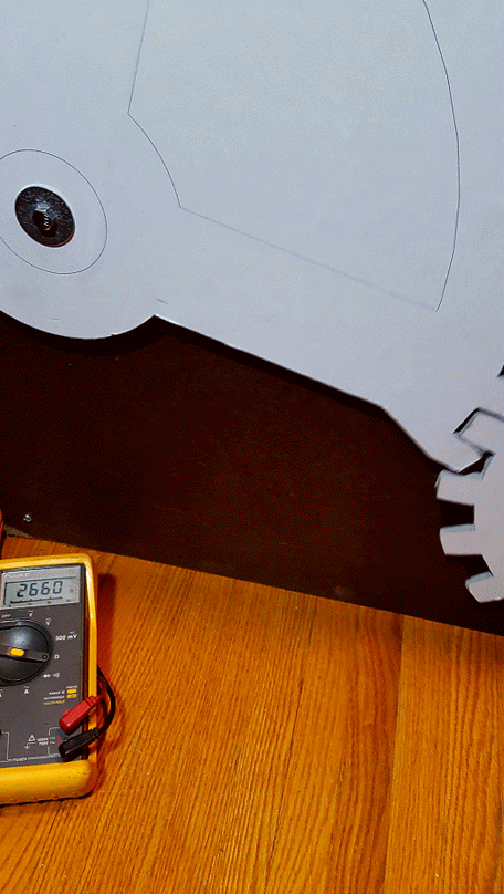
Changing gear position and resistance
The rest of the weekly summaries have been arranged by date.
Disclaimer for http://24hourengineer.blogspot.com/
This disclaimer must be intact and whole. This disclaimer must be included if a project is distributed.
All information in this blog, or linked by this blog, are not to be taken as advice or solicitation. Anyone attempting to replicate, in whole or in part, is responsible for the outcome and procedure. Any loss of functionality, money, property or similar, is the responsibility of those involved in the replication.
All digital communication regarding the email address 24hourengineer@gmail.com becomes the intellectual property of Brian McEvoy. Any information contained within these messages may be distributed or retained at the discretion of Brian McEvoy. Any email sent to this address, or any email account owned by Brian McEvoy, cannot be used to claim property or assets.
Comments to the blog may be utilized or erased at the discretion of the owner. No one posting may claim property or assets based on their post.
This blog, including pictures and text, is copyright to Brian McEvoy.
Comments
Post a Comment