Most of the building for the electrical work was done. The stations were each wired but the controller has not been wired or programmed yet.
Reed switches, which are activated by magnetic fields, were soldered to the ends of twisted pair wires salvaged from a network cable. Continuity tests were performed to make sure magnets attached to the 5/16" (8mm) rod would activate the switch from outside the PVC. Magnets were 6mm x 2mm in size. Wires from the reed switch were soldered to a three-position terminal strip.

The third position on the terminal strip was the positive lead of the motor. Negative terminals were tied together. Clockwise, looking down, rotation produced a positive voltage so leads did not have to be reversed. When wind turbines are attached they will have to be arranged so rotation is clockwise which should not be a problem. Reverse voltage could cause damage to the microcontroller.

Reed switches were fastened to the sides of the PVC adapters using plastic ties. Wires from the motor were also fastened in place using plastic ties. When the wires were secured test leads from a meter, set to measure continuity, were held under the screw terminals and a magnet was placed on the shaft running through the PVC adapter. Careful magnet positioning was done to get a reliable reading for each rotation of the shaft. After positioning the unit was reassembled.


Electrical work was done so each station was arranged on cardboard to protect the surface underneath in order to glue the terminal strip in place. Strong adhesive was applied to the motor mount piece which provided a flat surface suitable for mounting. Terminals strips were pressed into place, clamped and allowed to dry.


Files for Wind Generator Test Base:
The rest of the posts for this project have been arranged by date.
First time here?
Completed projects from year 1.
Completed projects from year 2.
Reed switches, which are activated by magnetic fields, were soldered to the ends of twisted pair wires salvaged from a network cable. Continuity tests were performed to make sure magnets attached to the 5/16" (8mm) rod would activate the switch from outside the PVC. Magnets were 6mm x 2mm in size. Wires from the reed switch were soldered to a three-position terminal strip.

Magnet finger used for testing a reed switch
The third position on the terminal strip was the positive lead of the motor. Negative terminals were tied together. Clockwise, looking down, rotation produced a positive voltage so leads did not have to be reversed. When wind turbines are attached they will have to be arranged so rotation is clockwise which should not be a problem. Reverse voltage could cause damage to the microcontroller.

Generating 0.23 volts by hand
Reed switches were fastened to the sides of the PVC adapters using plastic ties. Wires from the motor were also fastened in place using plastic ties. When the wires were secured test leads from a meter, set to measure continuity, were held under the screw terminals and a magnet was placed on the shaft running through the PVC adapter. Careful magnet positioning was done to get a reliable reading for each rotation of the shaft. After positioning the unit was reassembled.

Mounted reed switch

Wires fastened down

Magnet placed on rod

Magnet triggering switch from inside PVC adapter
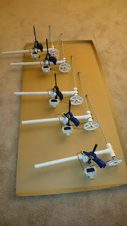
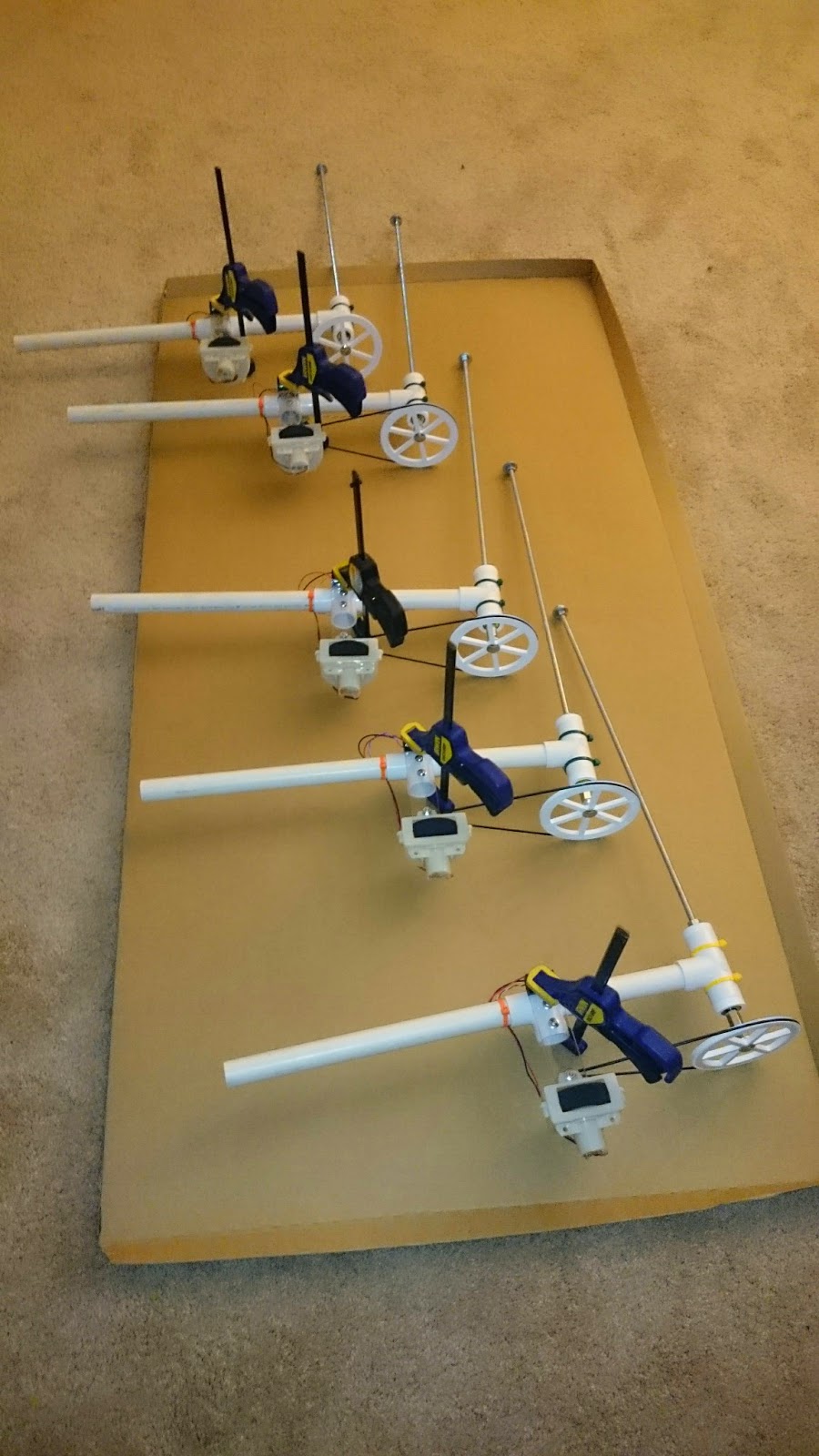
Electrical work was done so each station was arranged on cardboard to protect the surface underneath in order to glue the terminal strip in place. Strong adhesive was applied to the motor mount piece which provided a flat surface suitable for mounting. Terminals strips were pressed into place, clamped and allowed to dry.

Five wired stations

Glue for terminal strip
Terminal strips held in place to dry
Files for Wind Generator Test Base:
- Arduino code
- STL model for bearing holder no longer used but maybe useful for someone
- STL model for 3/4" PVC bearing adapter
- STL model for pulley
- OpenSCAD code
Design electrical- Build electrical for controller
- Debug program
Make program public- Test for usability
- Go to next phase and test turbine designs
The rest of the posts for this project have been arranged by date.
First time here?
Completed projects from year 1.
Completed projects from year 2.
Disclaimer for http://24hourengineer.blogspot.com/
This disclaimer must be intact and whole. This disclaimer must be included if a project is distributed.
All
information in this blog, or linked by this blog, are not to be taken
as advice or solicitation. Anyone attempting to replicate, in whole or
in part, is responsible for the outcome and procedure. Any loss of
functionality, money, property or similar, is the responsibility of
those involved in the replication.
All digital communication regarding the email address 24hourengineer@gmail.com becomes
the intellectual property of Brian McEvoy. Any information contained
within these messages may be distributed or retained at the discretion
of Brian McEvoy. Any email sent to this address, or any email account
owned by Brian McEvoy, cannot be used to claim property or assets.
Comments
to the blog may be utilized or erased at the discretion of the owner.
No one posting may claim claim property or assets based on their post.
This blog, including pictures and text, is copyright to Brian McEvoy.
2015-05-14 (Th)
2015-05-14 (Th)
Comments
Post a Comment