The week started with a sad realization that the keyboard design with the fancy folding key levers simply wouldn't work. A fresh design was conceptualized which had finger keys and thumb keys opposite each other so pressure wouldn't push the keyboard away. A soft prototype was just switches jammed into an eraser with four on one side for the fingers and three on the other side for the thumb.

A more detailed drawing was made which outlined the idea of how to make the enclosure. At that point it seemed logical to add a small battery and rely on the wireless. Having the battery in hand also meant that the keyboard could be removed and used independently of the wrist harness. This approach should have been used from the beginning.

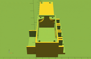
After sketching the enclosure with key mounting sockets it was modeled using the custom enclosure from a week ago. Spacing for the finger keys was kept standard but the three thumb switches were put right next to each other. Once it was printed all the switches were given wires and placed in the enclosure. Tension on the finger switches was enough to keep them in place but the thumb switches had to be glued.

Electronics were added. A small piece of stripboard was included to provide enough terminals for ground wires. There was plenty of room in the enclosure so wires were left unnecessarily long. 23A batteries were chosen because they are small and provide more than 5 volts. USB connection was ignored for the meantime but may be added later. USB connectivity would just mean extending the micro USB port on the Arduino to a USB micro connector on the outside of the box. A test text was sent to Gavin using the keyboard entirely wirelessly/


Programming for the servo controlling had been done a week ago but never put in a controller and tested. Thankfully the servo controller and keyboard controller were separated early on. A terminal board was given servo terminals and screw terminals to make it easy to attach two servo motors and three switches. The terminal board was then connected to the controller with salvaged wires. The program was put in but had a lot of bugs, some of which were due to the controller. These issues could have been avoided by using a larger Arduino Mini Pro but the difference in size, about half, may be worth the extra work.


Downloadable Files:
The rest of the weekly summaries have been arranged by date.

Eraser soft prototype
A more detailed drawing was made which outlined the idea of how to make the enclosure. At that point it seemed logical to add a small battery and rely on the wireless. Having the battery in hand also meant that the keyboard could be removed and used independently of the wrist harness. This approach should have been used from the beginning.

Drawing of keyboard enclosure
After sketching the enclosure with key mounting sockets it was modeled using the custom enclosure from a week ago. Spacing for the finger keys was kept standard but the three thumb switches were put right next to each other. Once it was printed all the switches were given wires and placed in the enclosure. Tension on the finger switches was enough to keep them in place but the thumb switches had to be glued.

Rotating model of keyboard enclosure

3D Print of enclosure
Electronics were added. A small piece of stripboard was included to provide enough terminals for ground wires. There was plenty of room in the enclosure so wires were left unnecessarily long. 23A batteries were chosen because they are small and provide more than 5 volts. USB connection was ignored for the meantime but may be added later. USB connectivity would just mean extending the micro USB port on the Arduino to a USB micro connector on the outside of the box. A test text was sent to Gavin using the keyboard entirely wirelessly/

Wired up keyboard

Test text to Gavin
Programming for the servo controlling had been done a week ago but never put in a controller and tested. Thankfully the servo controller and keyboard controller were separated early on. A terminal board was given servo terminals and screw terminals to make it easy to attach two servo motors and three switches. The terminal board was then connected to the controller with salvaged wires. The program was put in but had a lot of bugs, some of which were due to the controller. These issues could have been avoided by using a larger Arduino Mini Pro but the difference in size, about half, may be worth the extra work.

Digispark (Arduino) connected to a terminal board

Programming the Digispark over USB
Downloadable Files:
- Common OpenSCAD files
- Servo footprints for OpenSCAD.
- Arduino Code for wired keyboard
- Spreadsheet for chords.
The rest of the weekly summaries have been arranged by date.
Disclaimer for http://24hourengineer.blogspot.com/
This disclaimer must be intact and whole. This disclaimer must be included if a project is distributed.
All
information in this blog, or linked by this blog, are not to be taken
as advice or solicitation. Anyone attempting to replicate, in whole or
in part, is responsible for the outcome and procedure. Any loss of
functionality, money, property or similar, is the responsibility of
those involved in the replication.
All
digital communication regarding the email
address 24hourengineer@gmail.com becomes the intellectual property of
Brian McEvoy. Any information contained within these messages may be
distributed or retained at the discretion of Brian McEvoy. Any email
sent to this address, or any email account owned by Brian McEvoy, cannot
be used to claim property or assets.
Comments
to the blog may be utilized or erased at the discretion of the owner.
No one posting may claim claim property or assets based on their post.
This blog, including pictures and text, is copyright to Brian McEvoy.
Comments
Post a Comment